Sunday, November 28, 2010
MS8 (Working MCM) and future plans
During the week of the 22nd to 28th we were concentrated on making the most critical module for our project, as the 8th milestone required us to complete this part by Wednesday. As we have made most of the major parts to our MCM previously, we worked on the smaller parts in our module (for instance the L pieces connecting the top of the sweeping arm to the motor platform on which the platform will sit, or the pinion, which will allow the motion of our sweeping arm in the slot).The L pieces, mentioned previously, were very hard to machine, as we had to drill the holes after bending the aluminum pieces. The bending of the pieces complicated the placement of holes on the L piece, and initially led to some unwanted shaft misalignment, which was later fixed.
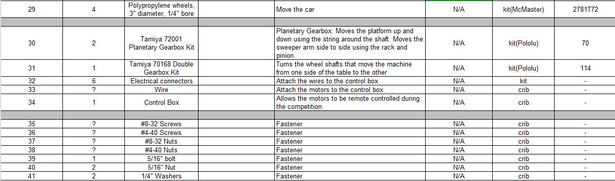
However, the MCM was only one part of the MS8 assignment. For MS8 we finalized our bill of materials and manufacturing process for the whole machine. For the materials, we are seeking to purchase a larger architectural tube (2 inches by 1 inch with 1/8th inch thickness) and also another 1/4 inch diameter aluminum rod for the motor/wheel shafts.
This is a small copy of our full bill of materials:


Here is a small copy of our full manufacturing plan:


We are currently looking forward to manufacturing the rest of the rest of the parts during the break (for other modules, including the frame, the scoop, and the wheels), as well as beginning to test out our design.
Sunday, November 21, 2010
Motor Plate and Revised CAD
We revised the solid model of our machine, including three motors (one on the top plate, one on the MCM and one on the bottom to drive car). We may need to buy another 24" long Al stock to build the car frame edges since the one in the kit is only 18" long so we cannot hold both scoop and sweeping arm inside of the car when drive it across the table.
Instead of making the platform moving with side wheels in the slot, we decide to make this simpler. We now have the platform with four little extrudes which slide between the car frame and the wood support.It will be easier to build and the function is still the same.
We inserted our control box on the top right corner since we have extra space there and it will not interfere with other modules.
We are going to use the double gear box to drive our car, instead of mounting it horizontally, we will build it vertically on a side wall since the space is limited and dont want the platform interfere with it which may not let the scoop and sweeping arm go down further.
The total dimension for our machine (maximum in each side) is
12.00 " (L) *11.05 " (W)*23.29 " (H).It meets the dimension requirement so far.


| We are going to finish manufacturing rest of our MCM, bill of materials and step by step manufacturing plan by next Wednesday for MS 8.For the MCM, we are going to use waterjet to cut the Al sheet and made several pillow blocks (L shapes) to let the shafts go through. |
Sunday, November 14, 2010
Update #2: Manufacturing Week
This week we worked on manufacturing parts for our MCM (most critical module) and refining our design so it can be more easily manufactured with the tools we have. Here are some photos of what we've finished manufacturing so far.
LOWER SWEEPER ARM (side and front view):


UPPER SWEEPER ARM(side view):
PLATE ATTACHED TO THE LOWER ARM TO INCREASE AREA (front view):

TO DATE MANUFACTURED MCM (front view):

Feel free to check back to Ren's post last week to check on our progress manufacturing thus far.
Besides manufacturing, we also worked on designing how our motor is going to move the MCM. Here is CAD we developed to show the basic idea. The clear plastic is a flexible tubing used to connect shafts of different diameters and to adjust for small amounts of misalignment between our shafts. This tubing connects the motor output shaft to the shaft with the pinion attached. By driving the shaft with the pinion we can move the pinion along a rack, thus moving the MCM. Please note: The platform that the motor is sitting on is the same platform that was located on the top of the MCM solid model last week.

Sunday, November 7, 2010
Update #1: Design Week
This is our official blog post about our progress of our slotbot machine design. This past week, we worked on some preliminary steps that are necessary to manufacturing our most critical module(MCM), and here are some of the drawings/work that we did:
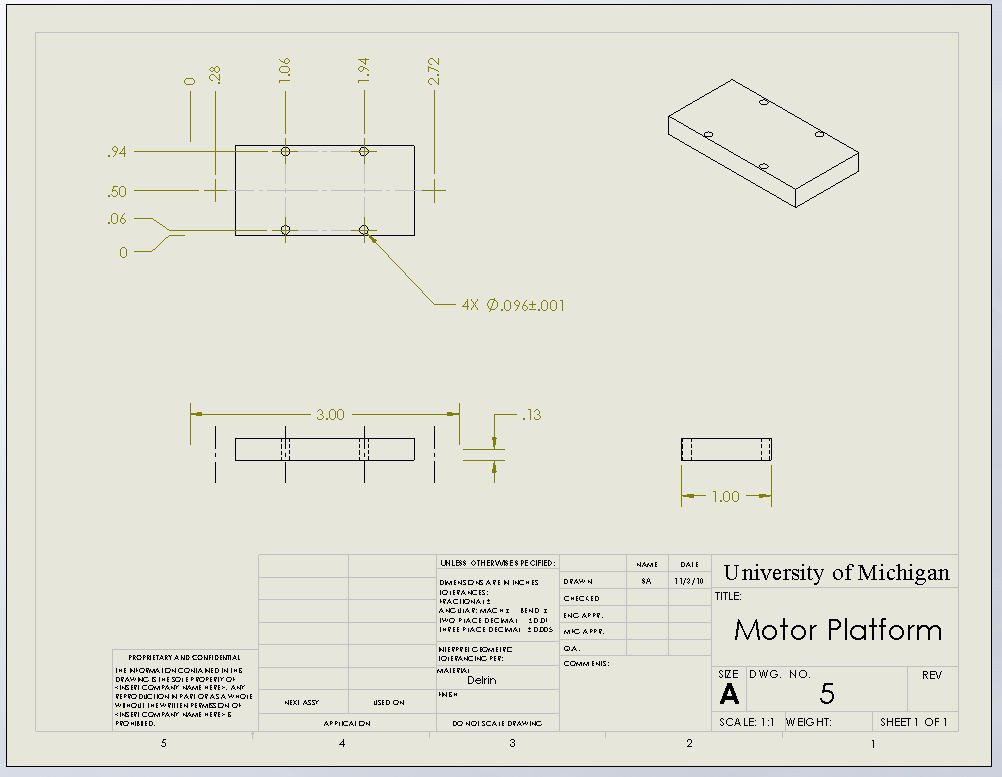
Drawing of the platform where motor sits on

The plate which is attached to the lower sweeper arm to increase area

The lower arm

Threaded rod for the lower portion and upper portion of the sweep arm top

This is the upper portion of our sweeping arm

Bill of materials

Step-by-step manufacturing plan

Here is the screen shot of solidwork for our Most Critical Module

Drawing of the platform where motor sits on
The plate which is attached to the lower sweeper arm to increase area

The lower arm

Threaded rod for the lower portion and upper portion of the sweep arm top

This is the upper portion of our sweeping arm

Bill of materials

Step-by-step manufacturing plan

Here is the screen shot of solidwork for our Most Critical Module

So yeah this is what we got for you so far. There should be pictures of the actual arm in about a week, stay tuned!
Subscribe to:
Posts (Atom)